
EMI Shielding for Rugged Electronics: Practical Steps Toward EMC
Most teams don’t lose time to EMI (electro-magnetic interference) because they “forgot shielding”. They lose time because EMI shows up as an integration problem—one that only becomes visible when the platform is fully assembled, cabled, mounted, and running at full duty cycle.
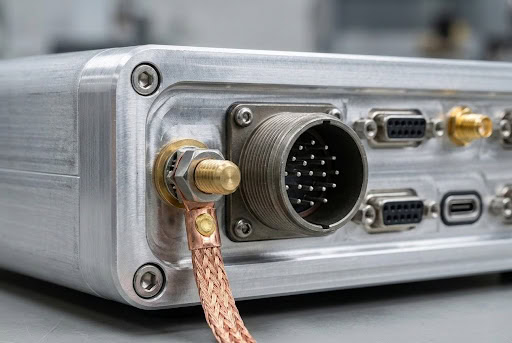
A compute card that behaved perfectly on the bench can start acting differently inside a rugged chassis. A harness that looked clean in CAD can become a noise antenna once it’s routed around power conversion and RF. Mechanical durability in a connector panel does not guarantee EMI performance. Without a deliberate electrical interface, shielding effectiveness will be compromised.
That’s the real shift from EMI to EMC (Electromagnetic Compatibility): Shielding is an architectural requirement, not a late-stage material add-on.
Stop thinking “shielding,” start thinking “system boundaries”
In rugged embedded computing systems, the most important EMI decisions usually happen at the boundaries:
- Where signals and power cross the chassis wall
- Where cables transition from internal to external harnessing
- Where panels, covers, and service points break up continuity
- Where thermal features (vents, airflow paths) introduce openings
These critical points determine whether the EMI shielding functions as a cohesive system or fails due to the cumulative effect of minor compromises.
If you’re trying to improve EMI protection, put your attention where the system connects to the outside world. That’s where EMC performance is most often made or lost.
Rugged chassis reality: continuity is a living thing
A rugged enclosure isn’t a static Faraday box. It’s a structure that lives through vibration, thermal cycling, maintenance access, and long-term wear. The shield you model is only as good as the shield you can keep electrically consistent over time.
In practice, the gap between “should shield” and “does shield” comes from interface details such as:
- Contact consistency across removable panels
- How repeatable the bonding paths are after reassembly
- How coatings, surface finishes and compression forces change over time
That’s why many “mystery” EMI issues aren’t truly mysterious—they’re the natural result of mechanical interfaces that were optimized for fit and finish, but not for electrical continuity.
This is where EMI shielding solutions become less about picking the right gasket or finish in isolation, and more about designing the whole enclosure interface so it behaves predictably across the system lifecycle.
Embedded platforms don’t fail EMC in the center—they fail at cutouts
The center of the chassis is rarely the worst offender. It’s the cutouts: I/O openings, connector plates, vent features, inspection covers, and anywhere the chassis has to make room for real-world needs.
Those features can act like “escape hatches” for emissions if they aren’t treated as EMI features from the start. And they can create susceptibility pathways too—especially when external cabling is involved.
A useful mental check during design reviews is: If EMI wanted to get out (or get in), where would it go first? The answer is usually an opening, a seam, or a connector boundary—not a solid wall.
Harnessing is often the loudest part of the system
A common surprise: the chassis can be doing its job, and the system still fails because the harness is doing something you didn’t intend.
Even with EMI shielding for electronics inside the enclosure, external cables can:
- Radiate noise generated internally (especially if termination/transition is weak)
- Pick up energy from the environment and feed it into sensitive inputs
- Couple noise between subsystems through shared routing and attachment points
When teams say “we already used shielded cable,” what they often mean is “we selected shielded cable”. That’s not the same as a completed shielding strategy. Cable shielding only becomes real at the transitions—where the shield meets the connector, backshell, and enclosure interface.
For many rugged embedded systems, the fastest EMC progress comes from treating harnessing as a first-class part of the embedded computing systems’ design, not a downstream packaging task.
The most productive EMC conversations are cross-discipline
EMC outcomes improve when mechanical, electrical, and integration teams share the same playbook early—before the platform is locked.
The questions that tend to pay off:
- Which subsystems are the most likely emitters at full load?
- Which signals are most susceptible (low-level analog, RF receive paths, timing)?
- Where do those paths physically run relative to power conversion and high-speed digital?
- What are the intentional bonding points and return paths—on purpose, not by accident?
- Which interfaces will be opened and reclosed during service, and how do we preserve continuity?
This is also where keyword-level “what is EMI shielding” becomes less relevant than “what makes this platform behave”. You’re not chasing a definition—you’re engineering repeatability.
Pre-compliance isn’t a milestone—it’s a feedback loop
A lot of EMC pain comes from learning too late. But you don’t need a perfect lab setup to gain clarity early. Even lightweight pre-compliance work can tell you whether you’re dealing with:
- a boundary issue (connector panel, opening, seam)
- a harness-driven radiator
- a conducted path that needs boundary control
- an integration/layout coupling problem
The value isn’t only “pass sooner”. It’s that early feedback keeps fixes structural and clean—changes to interfaces, routing, or enclosure details—rather than scattered, last-minute patches.
Building EMI shielding into the platform, not around it
If you want EMC confidence in rugged electronics, treat EMI shielding as a platform attribute: something engineered into the chassis, the connectorization, the harness strategy, and the system integration plan—not a material decision applied after the fact.
That’s the space Atrenne operates in every day—where rugged chassis design, embedded platforms, and integration details meet. The advantage of a platform-and-integration approach is that it aligns the mechanical reality (seams, serviceability, thermal constraints) with the electrical reality (bonding, return paths, cable transitions) so EMI control holds up in the lab and in the field—without overbuilding the system or impacting schedules.